Reverse Engineered Specification for Shimano Stepper Motor EM-286 STH-039H112-06
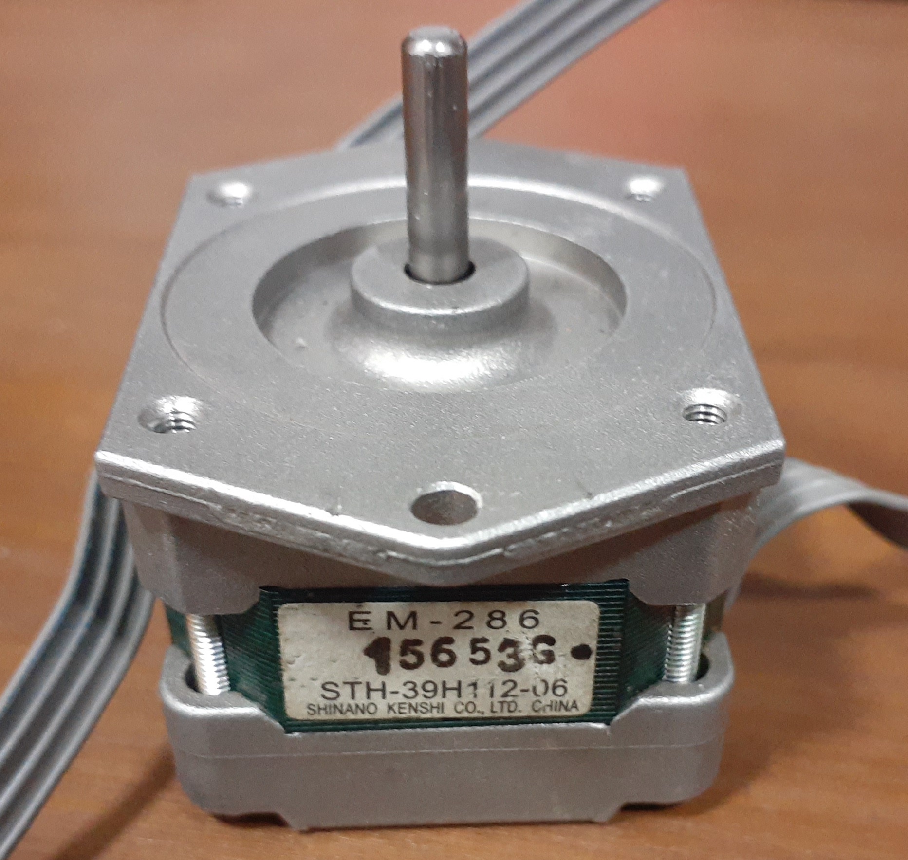 The EM-286 Shimano STH-39H112-06 is a stepper motor recovered from old FX880, FX890, FX2180, and other EPSON matrix printers. To use it in a personal 3D printer project, I reverse engineered some of its electrical and mechanical characteristics. It appears that there is no datasheet of it on the internet. I’m documenting the specs here for future reference. Feel free to use and propose any corrections for the parameters below.
Mechanical characteristics
| Characteristic | Value |
|---|---|
| Form factor | NEMA17 |
| Dimensions | 38.8 x 38.8 x 32.5mm |
| Weight | 157g |
| Space between screw holes | ~31mm |
| Shaft diameter | 4mm (note that standard 3d printer pulleys are 5mm in diameter) |
| Shaft length | 14.5mm |
| Step angle | 3.75˚ (an uncommon value, but I confirmed that) |
| Steps per revolution | 96 |
The step angle is a bit unusual compared to standard stepper sold in 3D printers nowadays (they have 1.8˚ per step). Use the following formulas to compute steps per mm values to configure the firmware:
Direct attached to leadscrew and using 1/16 micro-stepping:
steps_per_mm = 96 * 16 / thread_pitch.
Example for a standard T8 leadscrew with 2mm thread pitch: 96 * 16 / 2 = 768 steps per mm. Max resolution in mm = 1/768 = 0.0013 mm or ~1.3 micron.
Belt driven using 1/16 micro-stepping:
steps_per_mm = 96 * 16 / (teeth * tooth_pitch)
Example for a 20 teeth pulley and GT2 2mm belt: 96 * 16 / (20 * 2) = 38.4 steps per mm. Max resolution in mm = 1/38.4 = 0.026 or ~26 micron.
Direct extruder using 1/16 micro-stepping:
steps_per_mm = 96 * 16 / (gear_diameter * π)
Example for a 11mm diameter filament gear: 96 * 16 / (11 * 3.1415926) = 44.448 steps per mm. Max resolution in mm = 1/44.448 = 0.022 or ~22 micron.
If using gear or pulley reduction, multiply the result by the gear ratio.
Electrical characteristics
Here are the values I used to drive the motor. I consider them “safe” as it can operate barely warm (almost the same ambient temperature). Please don’t consider them as maximum or minimum ratings that you find in an official datasheet.
| Characteristic | Value |
|---|---|
| Type | Bipolar |
| Resistance per coil ⁽¹⁾ | 15.1 Ω |
| Voltage used | 12V ⁽²⁾ |
| Theoretical current at 12V per coil (Please see ⁽³⁾ and current limiting below) | 0.8A ⁽³⁾ |
| Driver | A4988 |
| A4988 current limiting voltage | 0.27V |
I limited the current feed to the motor using the potentiometer in the A4988 board. To reduce noise, I used the minimum current capable of moving the 3d printer axis without skipping steps. The voltage measured between GND and the top of the potentiometer was 0.27V. According to Pololu formula and considering Rs = 0.2Ω (cloned version), the driver will feed 0.168A to the motor. The amperage read in series with the VMOT pin was 0.17A and was very close to the formula value. Genuine A4988 has Rs equals to 0.068 or 0.05Ω.
⁽¹⁾ In the default cable, coils are pins 1 and 3, and 2 and 4. Thus, to drive it using A4988, you have to connect pins 2 and 3 interchanged.
⁽²⁾ The service manuals for FX880 and FX890 indicate a supply voltage of 35V. However, it is also mentioned that the current was limited, depending on the print speed.
⁽³⁾ I believe that 0.8A is too much to move a 3D printer axis. It probably makes more sense to improve axis components. In my tests, this motor becomes warm starting at 0.4A so better to stay on the safe side.