A Wireless 3D Gamepad DIY for Your Robots: Model, Circuit, and Firmware
 This is a DIY Wireless 3D Gamepad designed for controlling an arm robot. It was developed under a technological research project¹ in Brazil at the Federal University of Jataí - GO². The project aims to build very low-cost robots to use in educational activities in Brazilian public schools.
Although there are many readily available gamepad or similar wireless controllers, and their quality is a must, the cost of bringing several of them to enable a class activity didn’t fit our budget. By the way, we also want to empower the students and encourage them to pursue STEM careers, and nothing better than presenting something they can create themselves in a maker lab!
Summary of Characteristics
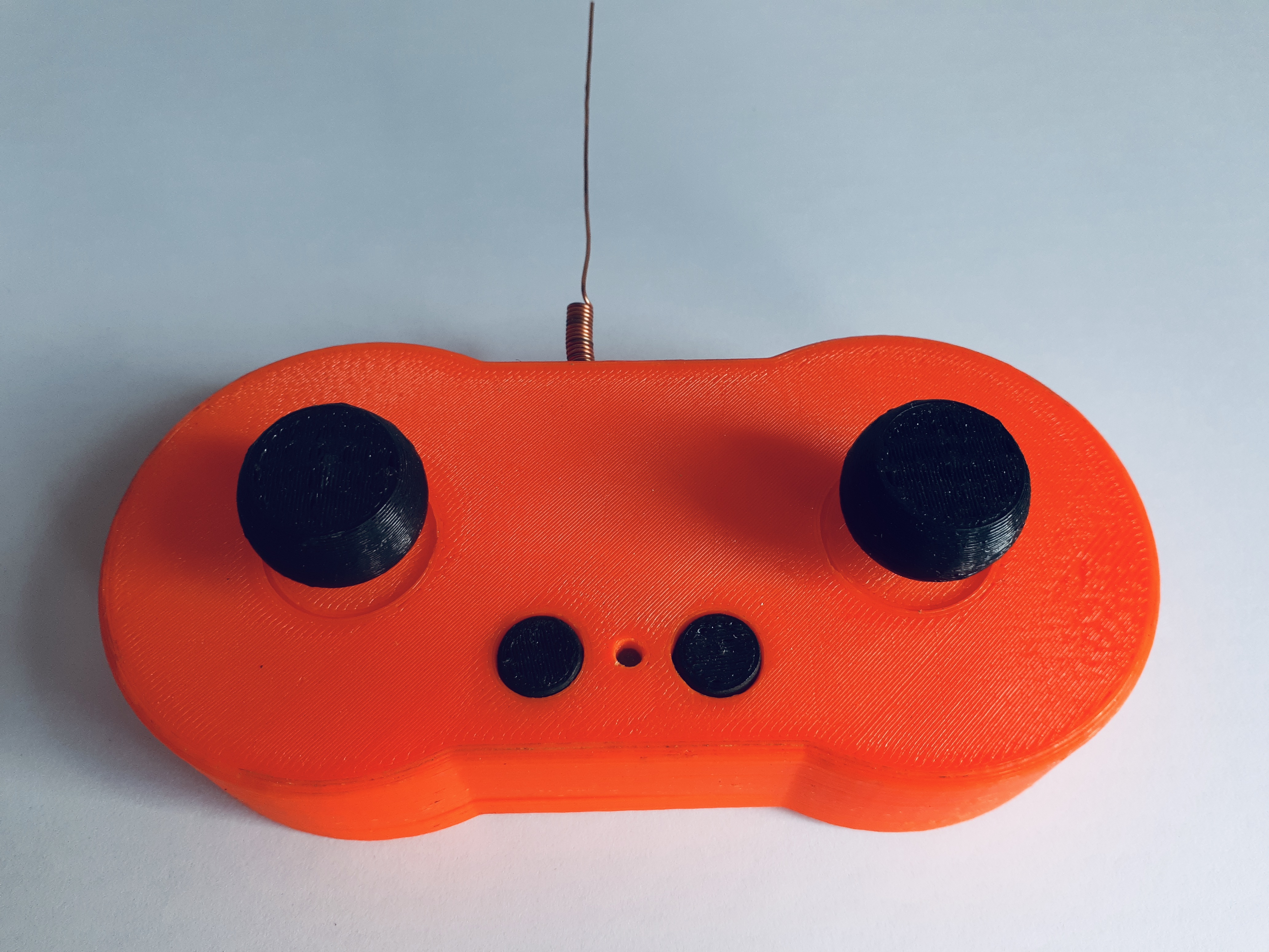
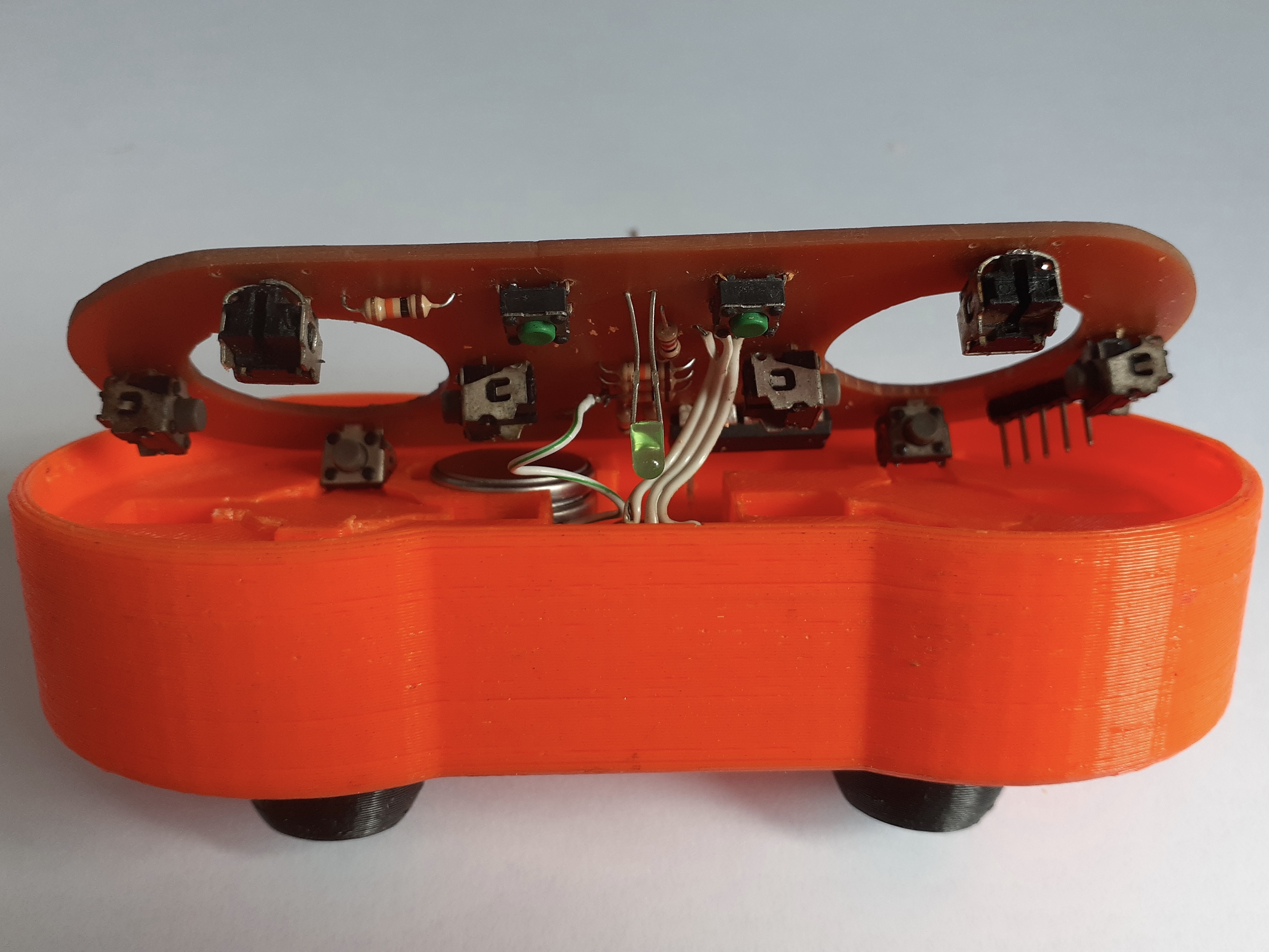
The 3D Gamepad has two thumbsticks, each one pressing four buttons disposed in the left, right, top, and bottom directions. There are two additional buttons in the center and a feedback light that flashes in every move. Its mainboard uses a small PIC processor powered by two CR2032 3V button cells that sends the pressed buttons through a standard 433 Mhz RF module.
Main characteristics:
| Dimensions (WxDxH), without antenna | 127x60x40mm |
| Filament used to print | ~50g of ABS, PLA, or PETG |
| Printed pieces | Main frame, two rounded buttons, and two handles |
| Battery | Two CR2032 in series, 3V each |
| Processor | PIC, Model 16F676P |
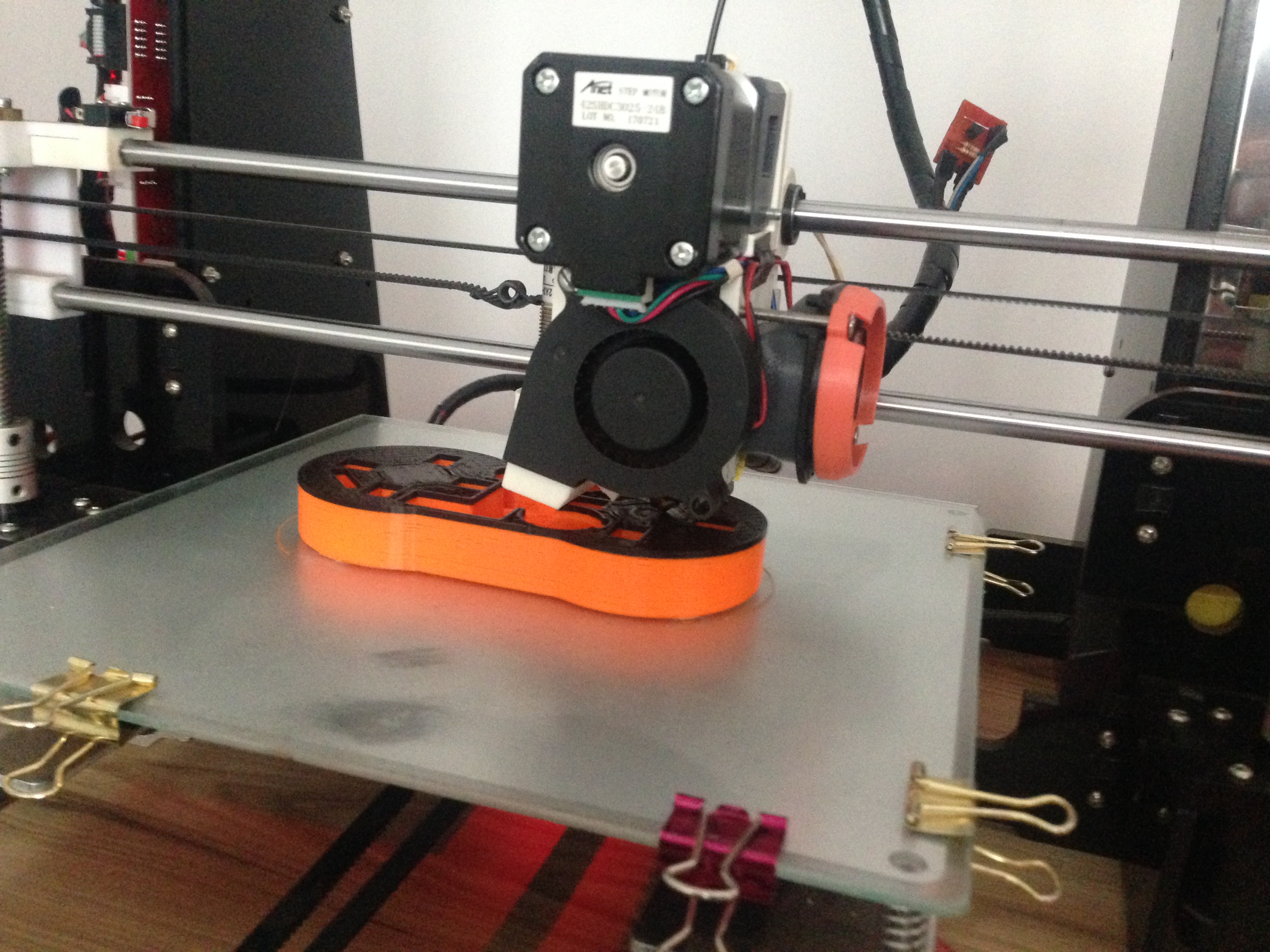
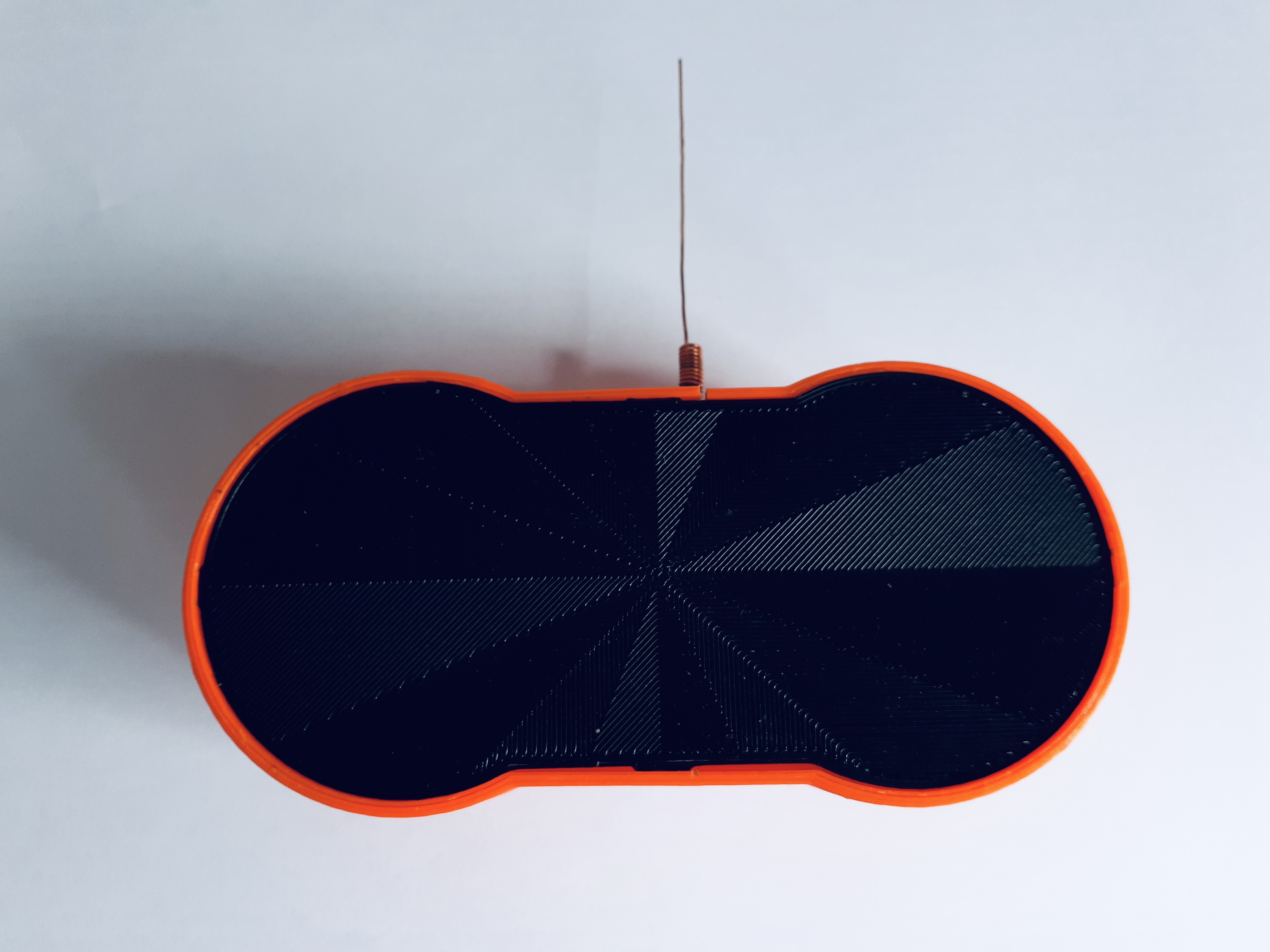
The Print-In-Place 3D Model
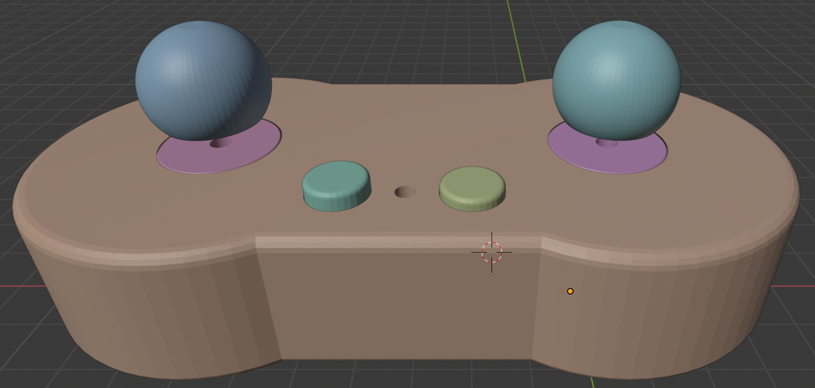
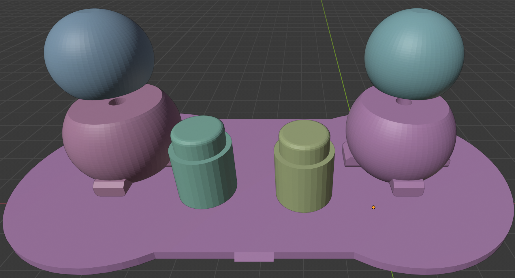
The pictures above show a model of the assembled gamepad (left) and its internal pieces (right). There is no need for support when printing, and the assembling requires no screws or glue.
The pieces to 3D print are:
- The external frame, in brown, and the thumbstick eye-balls that together compose a print-in-place object (i.e., you print it in position, not separated),
- Two round buttons, and
- Two thumbstick handles.
The most challenging piece to print is the frame as sometimes the thumbstick eye-balls fuse to it. However, you can successfully print it with 0.2 or 0.3mm layer height, using ABS or PLA, in a well-calibrated printer. Slow it down in case of fusion and tune the retraction option. I printed it successfully in a very customized Anet A8, and hence, it should be not that difficult in a better printer.
This .stl file contains all needed objects in its correct orientation.
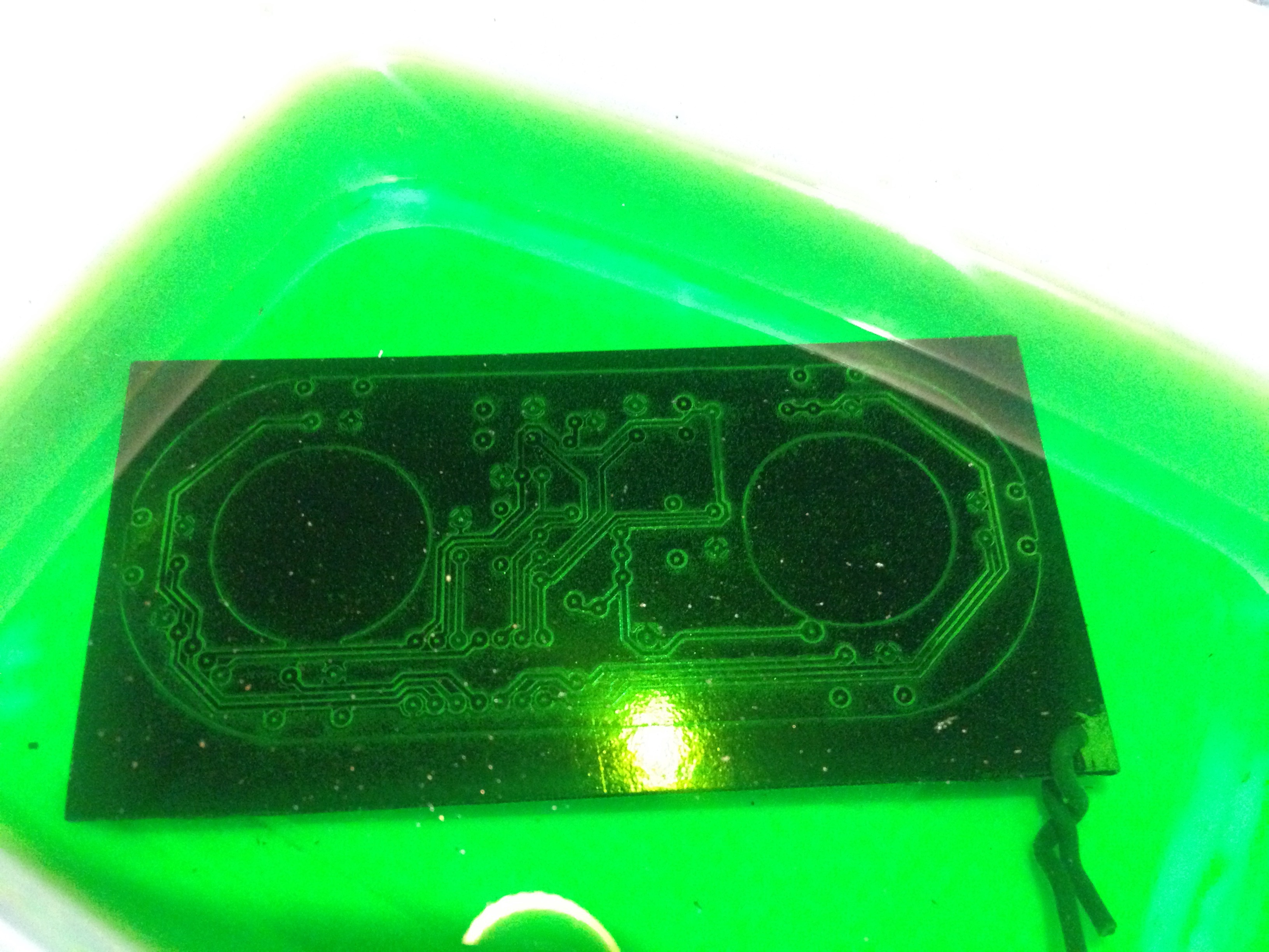
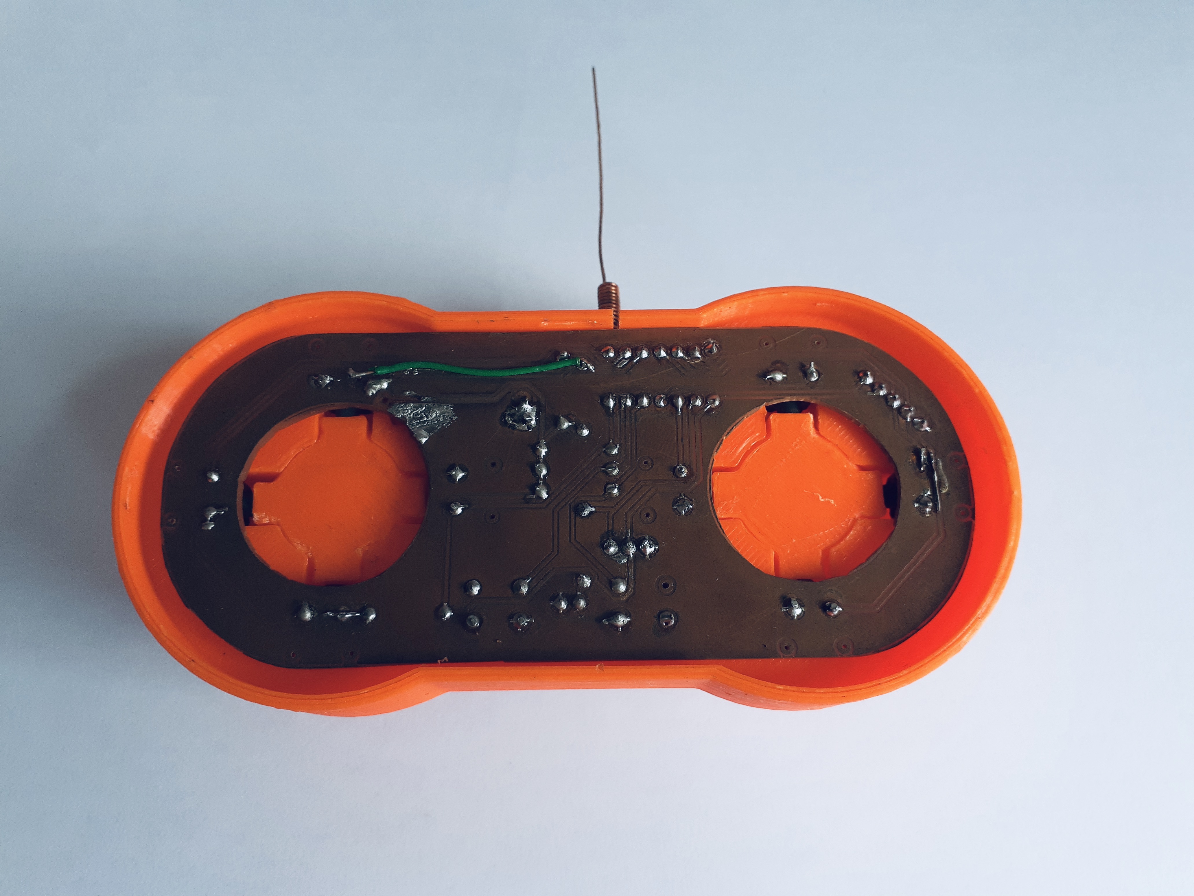
The Circuit Board
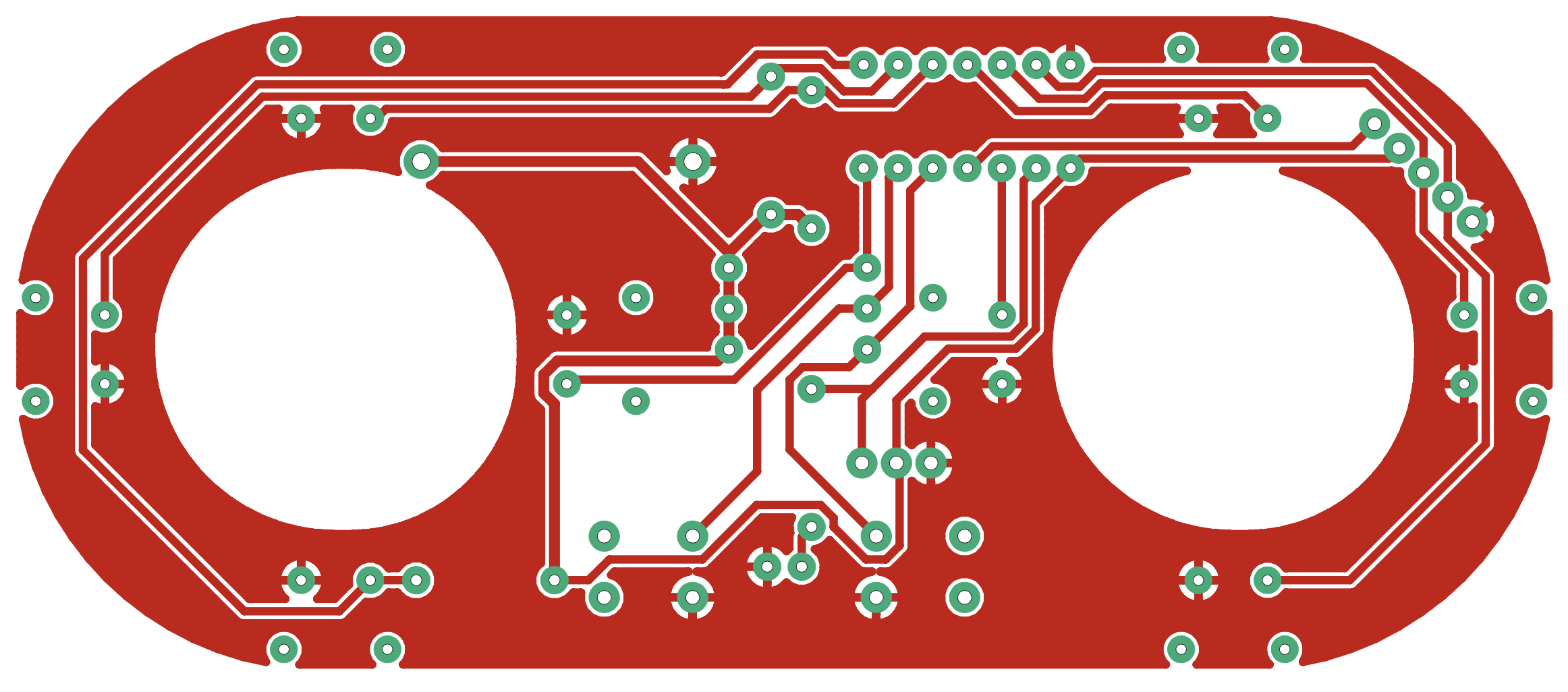
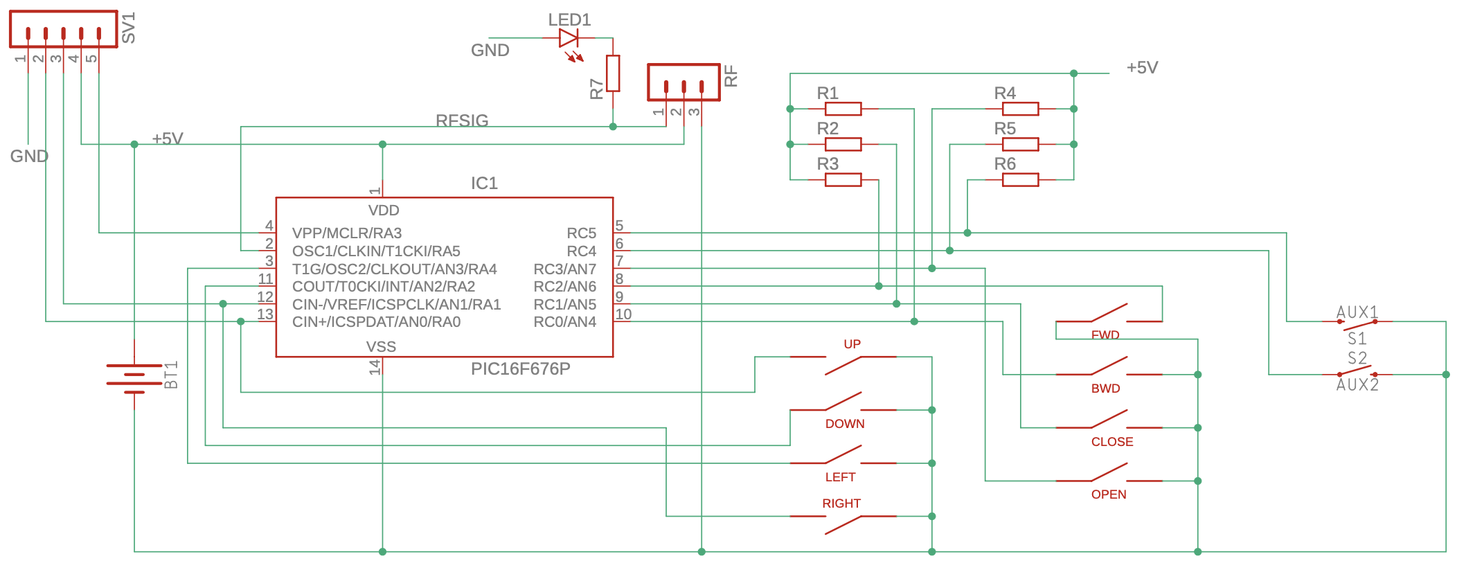
The PCB format fits the 3D printed frame. It has rounded sides, and two holes of 26mm diameter like pictured above. The holes free the movement of the thumbstick eye-balls enabling their pads to touch the buttons.
The board has a pin header to program the processor using the PIC high-voltage protocol, that is, the one you provide ~10V DC on the MCLR pin. What motivated us towards the choice of a PIC was only the price. For sure, an Atmega processor is a favorite option nowadays and has a more accessible programming interface. However, it costs almost twice the price where we live. Options include some Asiatic processors, like the ones from Padauk, that are even less popular but are even cheaper. If you have some indication, we thank you for commenting below.
The list of components you will need to make the board is (Bill of Materials, BOM):
| 8 | 6×6x5.5mm Right Angle Micro Momentary Tactile Push Button, like this one https://ebay.to/3bno2Ot |
| 2 | 6x6x5mm Momentary Tactile Push Button, like this one https://ebay.to/2wztAqt |
| 1 | LED 3mm with long legs |
| 6 | 10 kΩ resistors, 1/4W was enough |
| 1 | 1 kΩ resistor, 1/4W was enough |
| 12x6cm | Single sided copper board to etch |
| 1 | 433 MHz RF module + antenna, like this one https://ebay.to/2UgkPur |
| 20cm | Enameled copper wire gauge xxx for antenna |
Of course, depending on your preferred way of making a board, you should add materials to etch and solder the components on it. An option is to order it pre-fabricated from companies like JLC PCB or PCB Way. Just use the provided Gerber files below when ordering.
To mention an alternative, you can replace the wireless module by a two-wire cable wired to GND and RFSIG if wireless turns to be faulty for your application due to low fidelity, weak signal, or bad antennas.
The Software and Wireless Protocol
The wireless protocol is a pulse-period encoded system, based on the protocol designed in https://www.romanblack.com/RF/cheapRFmodules.htm. Using a default radio library was not an option for us due to choice of the PIC processor.
To balance the receiver gain circuit and improves the transmission, we send:
- a preamble containing high (170ms) and low (80ms) pulses ten times,
- two bytes indicating the pressed buttons, one button per bit: a zero bit sends a 20ms high and 80ms low signal, and a one bit sends a 70ms high and 80ms low, and
- a byte containing a CRC8 of the two previous bytes.
You can find additional details of the protocol in the source code. Fell free to ask anything.
The zip file below has the firmware coded in C language and a pre-compiled version of it using SDCC for PIC16F676P (.hex file). There is also an Arduino project and a python file that you can use to transfer the firmware to the PIC. All the credit and origin of the source files are in the comments. I made very little changes compared to the original, mainly to make them work in my environment.
Of course, the device that you want to control should receive and interpret the gamepad signal. Below, there is also an example of how to accomplish that in an Atmega processor.
Additional Assembled Photos for Reference
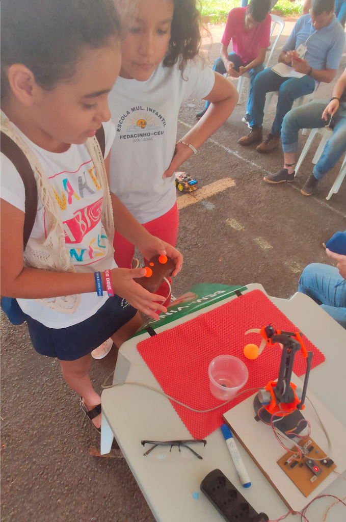
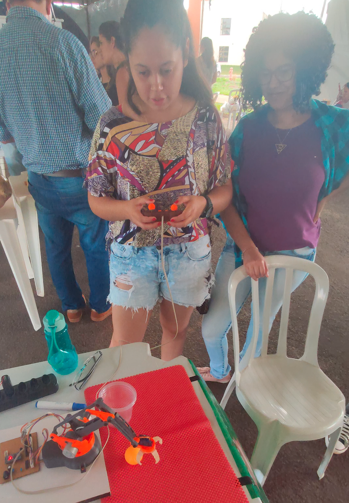
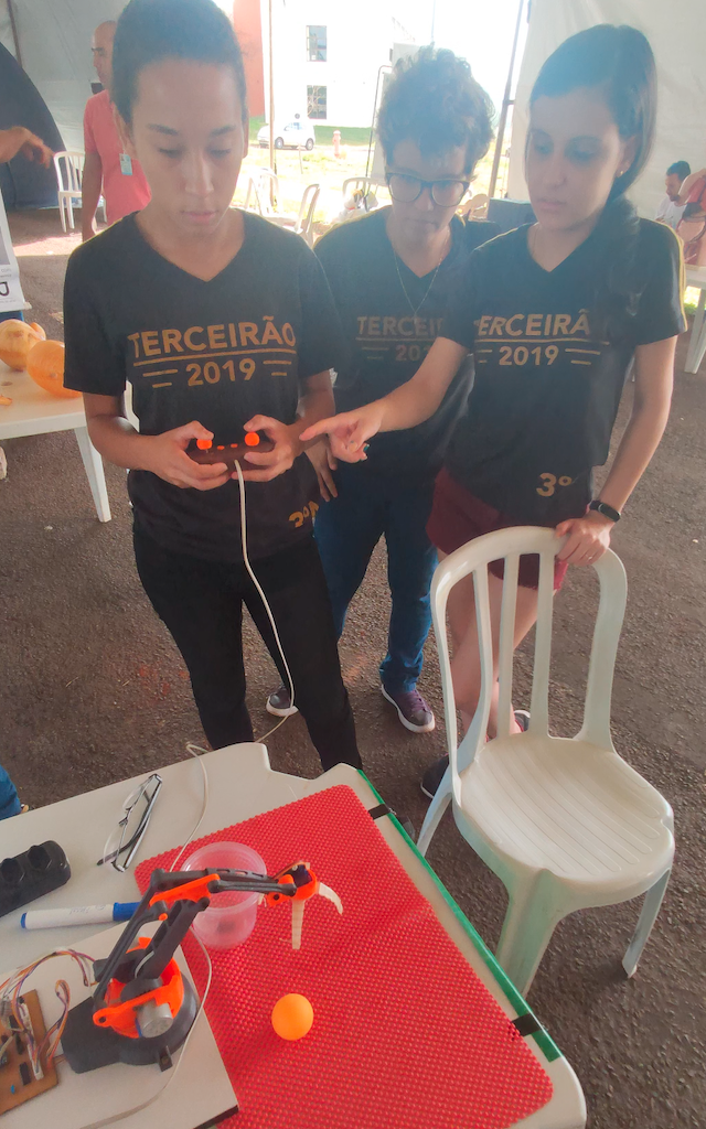
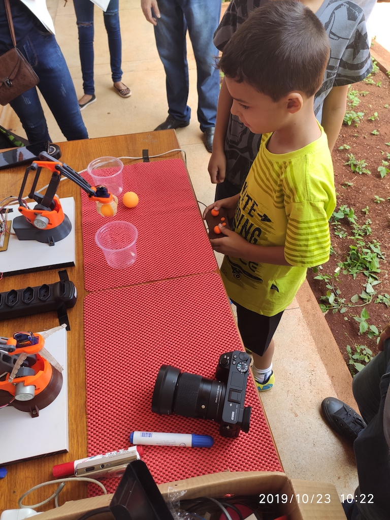
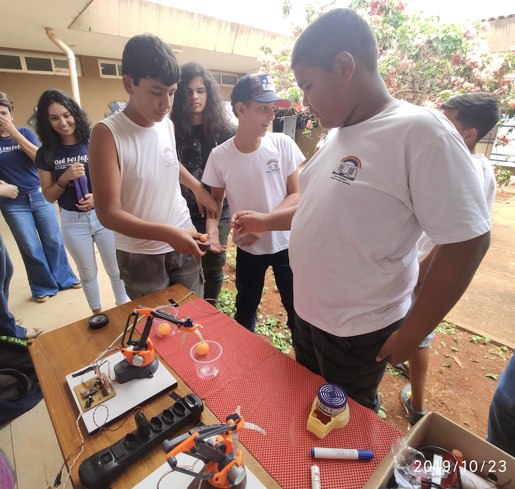
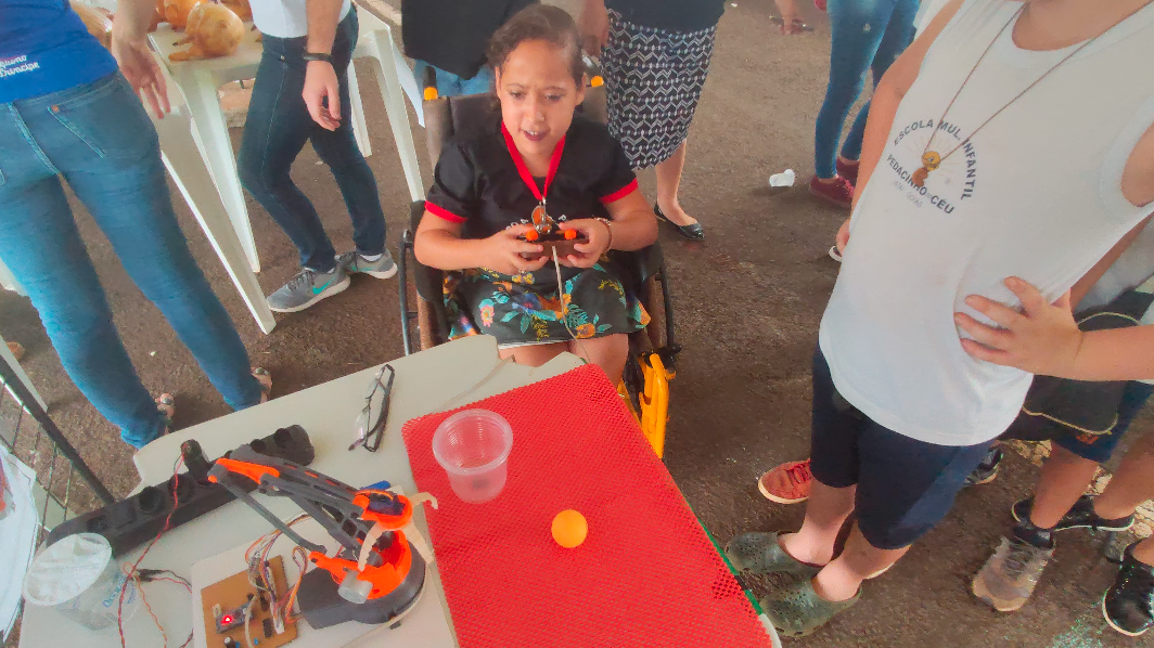
The Joy of Seeing it in Action and Recruiting Future STEM Scientists!
All the hard work through these intricate pieces of design and software deserves a reward! As part of a larger project, we used this gamepad to control robots presented in science fairs at our university. We encourage boys and girls from public schools and of any age to use it and complete a challenge with ping-pong balls. See it in action below!
Points for Improvement
Although there are many areas of improvement, the ones we like to highlight are:
- Add a power switch: although the PIC processor is programmed to sleep, an on-off switch will be better than removing the battery when not in use;
- Turns axis pads adjustable: the contact of the axis pads with PCB buttons can skip hits, depending on the pressure applied by the user. Adding little holes for small screws in the pads will allow tuning the contact and make it less faulty.
- Improve the battery slot: We did the initial PCB design with a button cell slot in mind, but it turns out to be tough to find it in the local market. Maybe the slot in the frame should be remodeled to accommodate another type of battery, e.g., a rechargeable one, with more straightforward contacts to solder in the PCB to interface with it.
¹ Especificação e Construção de Protótipos Funcionais de Kits Robóticos de Baixo Custo para uso em Processos de Ensino-Aprendizagem.
² Former Regional Jataí of Federal University of Goiás.